This page descirbes how to make your own FabFTDI cable (i.e. USB to serial converter). FabFTDI is DIY version of FTDI cable that can be made in fablab. It uses an Atmega16U2 microcontroller and is based on USBtoSerial example of LUFA library. Figure below shows the schematic diagram of the the FabFTDI circuit:
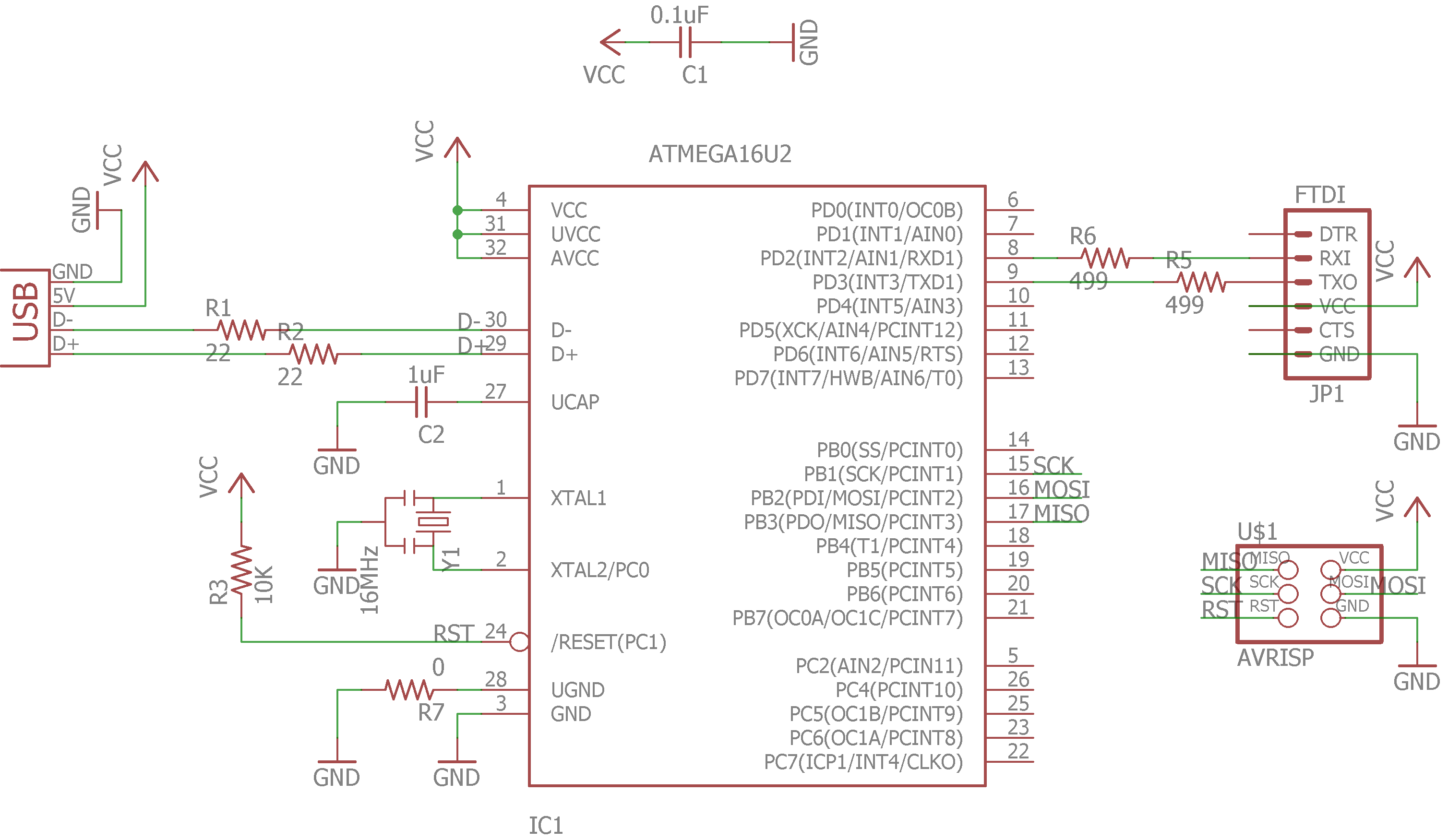
Figure: Schematic circuit diagram of FabFTDI.
The FabFTDI is powered through USB port which provides 500mA at 5V. The USB controller needs a precise clock, therefore, an external 16MHz resonator is used as a precise clock source (note- eventhough the resonator is not as precise as a crystal, its precision is sufficient for a USB 2.0 full speed device). The FabFTDI is a USB 2.0 Full-speed device and support upto 38400bps of serial communication. The Unix and Mac OS doesn not require any drivers, however, a driver is required for windows operating system (more on this later).
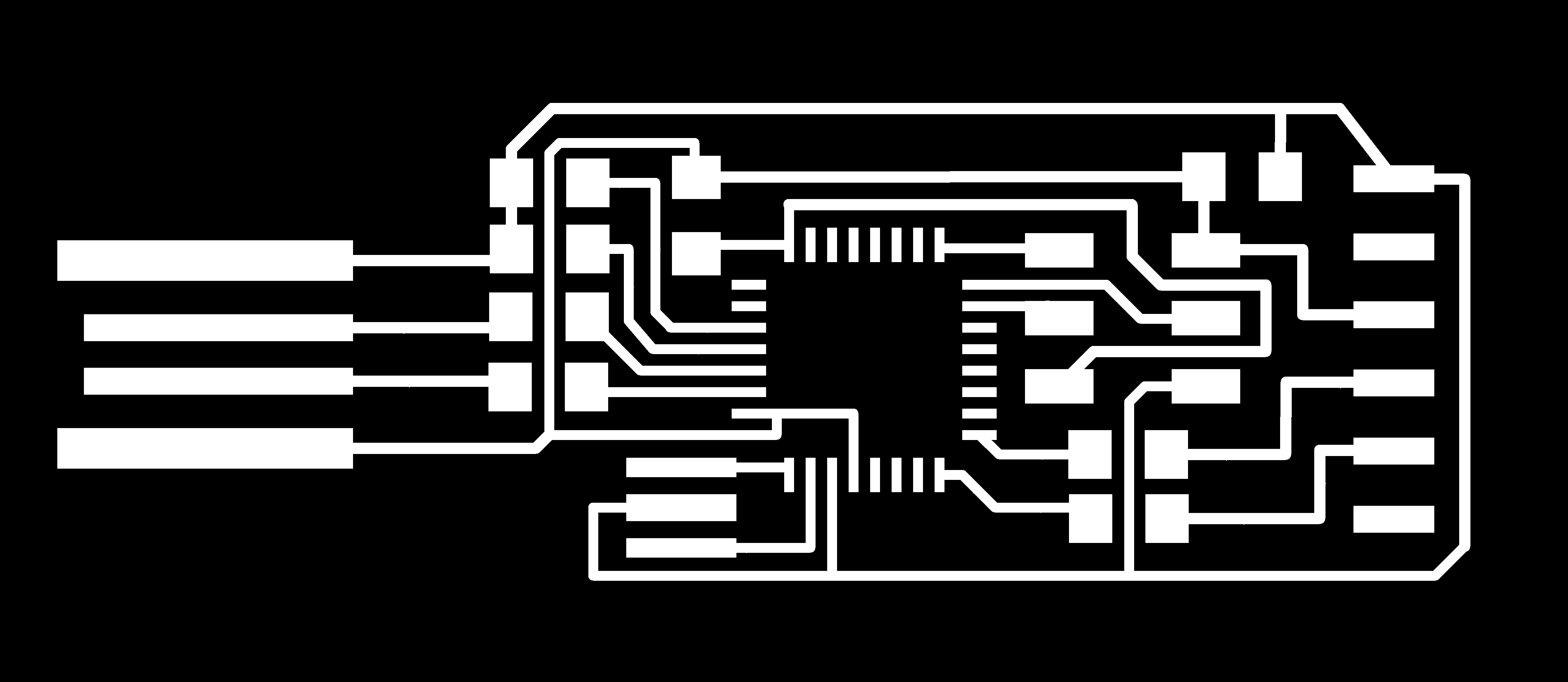
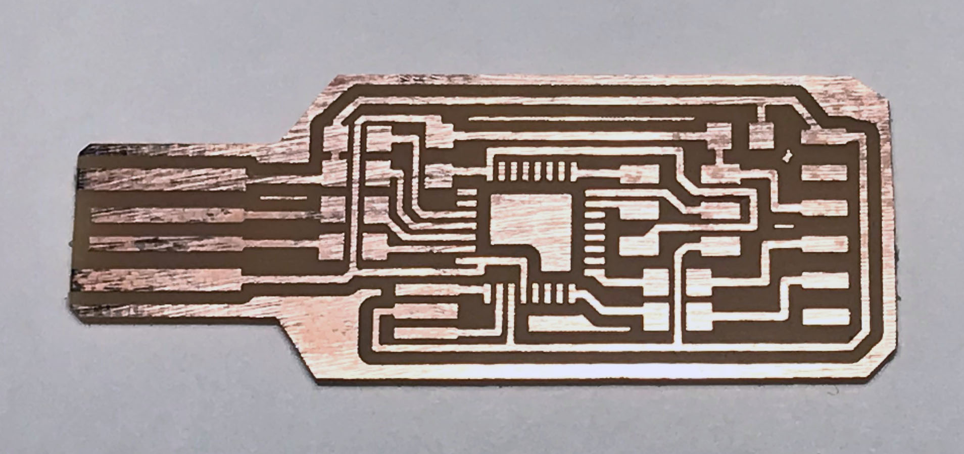
Figure below shows the FabFTDI board design.
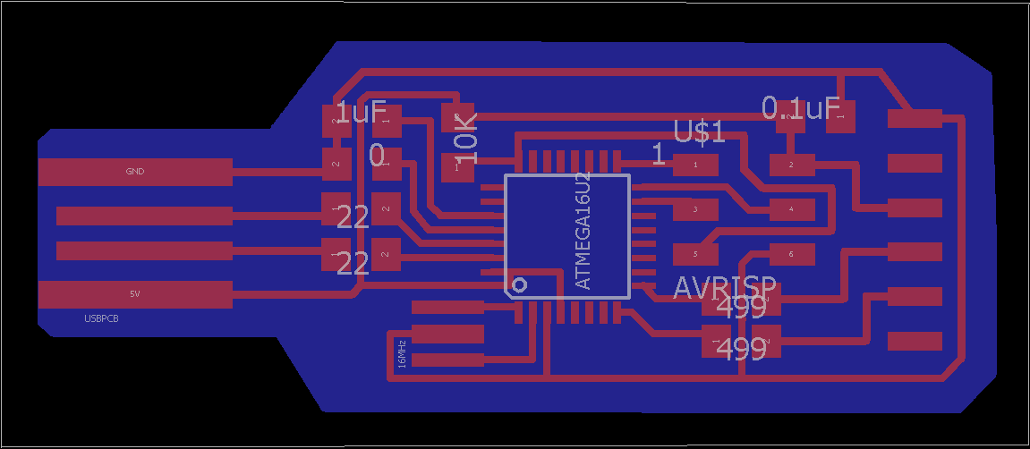
Figure: Board design of FabFTDI.
Download the PCB trace file and outline file from the links below:
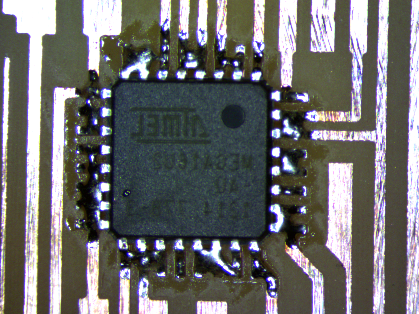
Figure below shows the milled board. Inspect for error and make sure no wires are short-circuiting.
For stuffing FabFTDI board you will need following components:
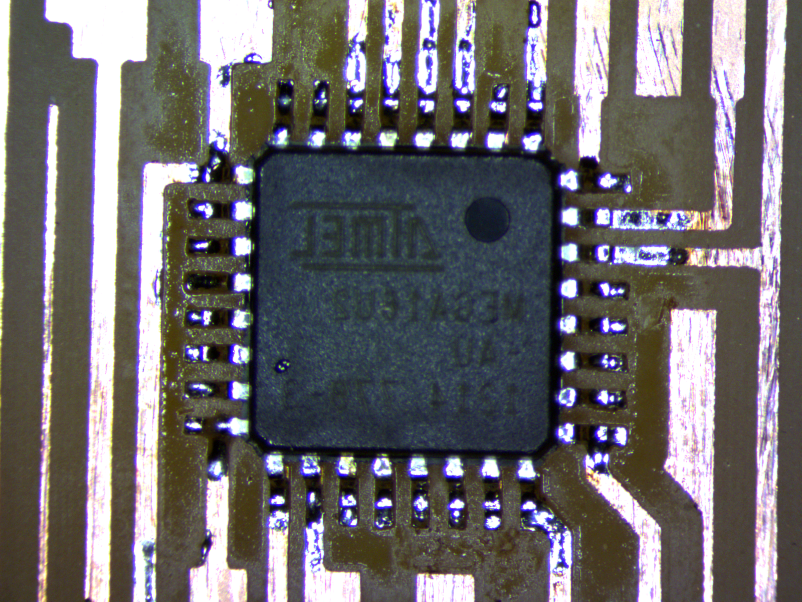
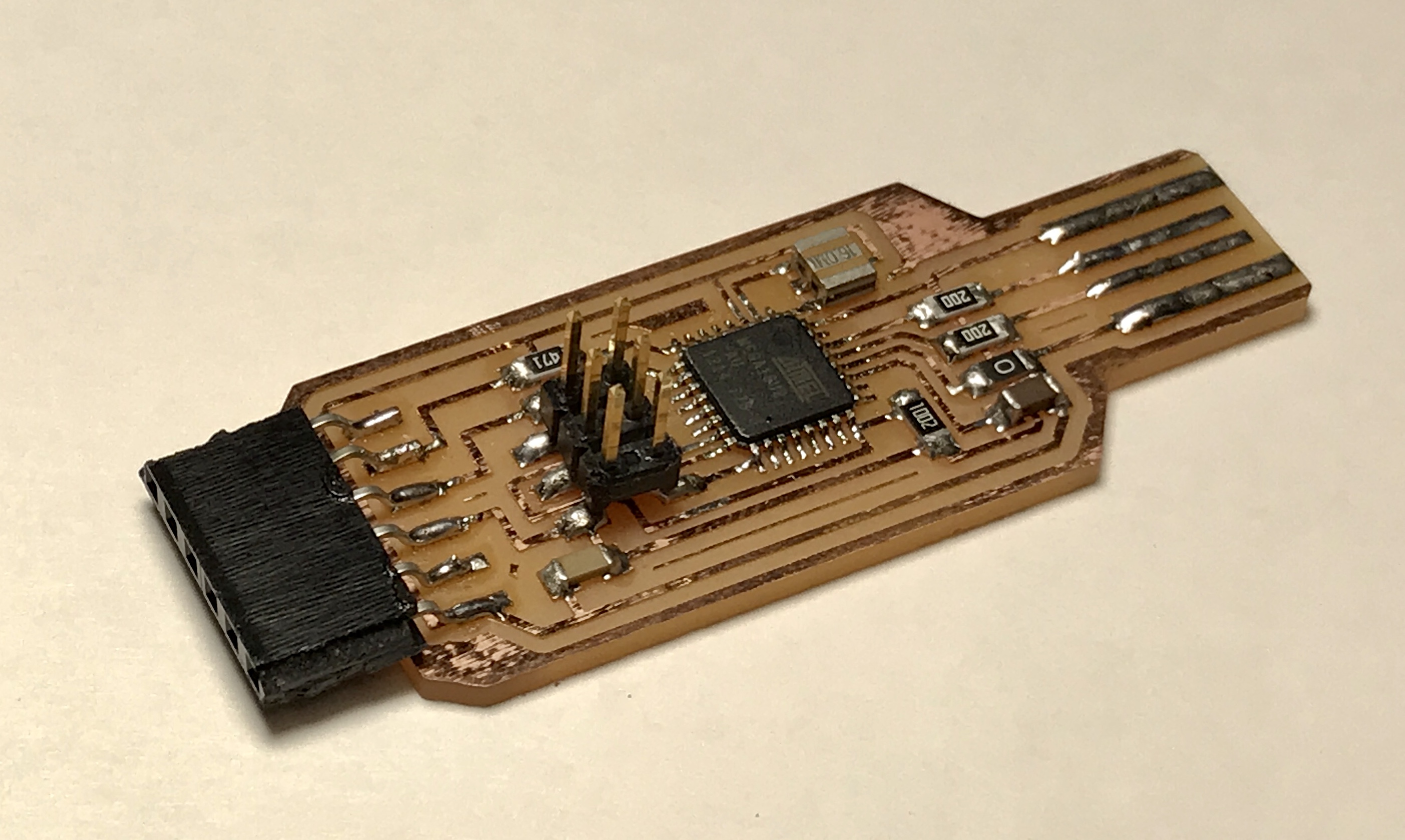
It is recommended to start with stuffing smaller and difficult components first and then bigger and easy components such as connectors. For FabFTDI, start with soldering the micro-controller as it is tricky since the pins are very close to each other. Here, I am showing an easy way to solder the microcontroller. First, carelessly solder all the pins to the pads and then use copper braid to remove excess solder.
Once the micro-controller is soldered. Solder other components like resistors and capacitors. Finally, at last, solder ISP connector and FTDI connector. Figure below shows my stuffed board.
$ make program-usbtiny
$ make program-avrisp2(Note - The code is pre-complied, however, if you want to recompile it locally before flashing it into your FabFTDI board execute the following commands:
$ make cleanRecomplie the files again
$ makeProgram the newly created hex file to your FabFTDI board.
$ make program-usbtiny
Once you connect the FabFTI to your computer, both Mac and Unix operating system should detect it right away without needing any driver. However, Windows operating system would require a driver (more on this later). Follow the instruction for your operating system to check if the FabFTDI is detected sucessfully
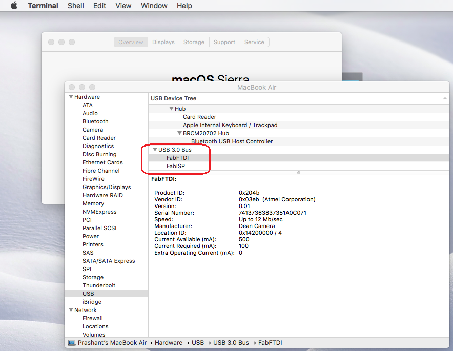
Click on the apple icon on the top-left of the screen and then click on "About this Mac". A "system information" box will open, click on the "system report" button which will open another window. On the left of the window, scroll-down and click on USB. Here you should see FabFTDI listed. See the image below for reference.
In ubuntu, lsusb command is used to list all connected usb devices. Open a terminal and type
$ lsusb
Windows operating system need a driver for the FabFTDI to work. When you will connect the FabFTDI to your Windows PC, it will be registered as an "unrecognized device". Follow the instructios below to install the driver.
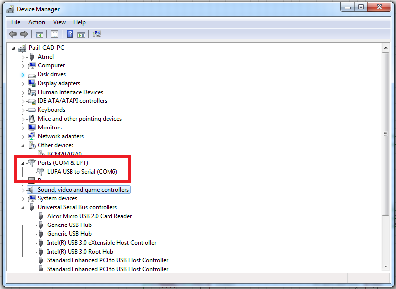
Once the drive is succesfully installed, the FabFTDI should be listed as "LUFA USB to Serial" in windows device manager. Check the image below for reference.
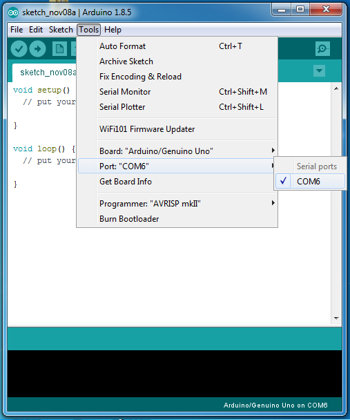
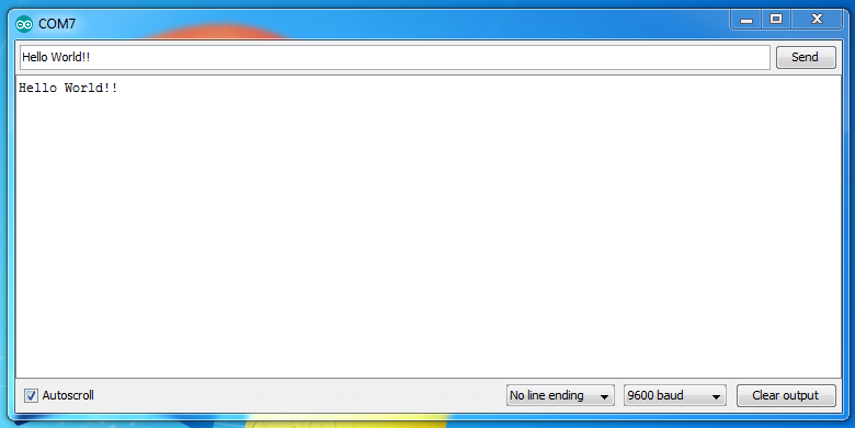
We are almost done! To check that our FabFTDI is indeed functining as a FTDI cable, we would need a serial terminal through which we will send some characters to our FabFTDI. The easiest way I have found is using the serial monitor that comes with Arduino IDE. Below are the instructions to test your FabFTDI:
Sometime things don't workout the way we want them to, If your FabFTDI is not working, try following things
